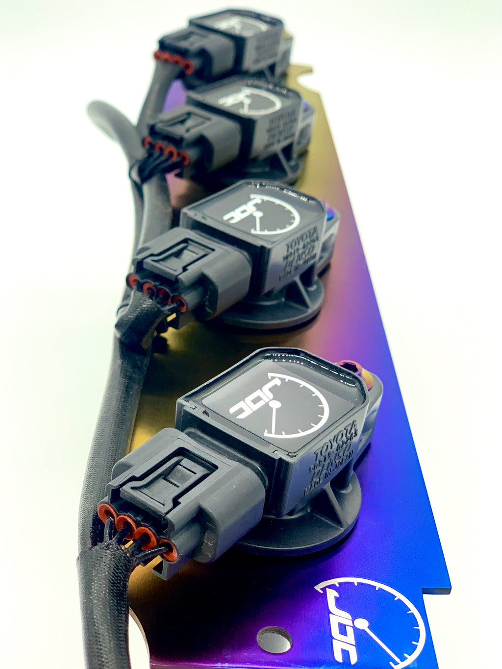


Insert the “Ground” wire into the wire sheath and connect it to the Denso connector “Ground” port.Starting with the set of shorter wires, insert the “+12V” wire into the proper length wire sheath along with the heat shrink and connect it to the Denso connector “+12V” port (see pin guide below).Group the shorter and longer wires together coming from the Evo male connector and pull them to one side of the connector to separate them from each other.Cut the wire sheath in sizes to cover the wire starting with the shortest wires first.If one is shorter than the others, you do not have it snapped in, and it will result in a misfire. The pins should be the same length when looking into the end of the connector. Give the wires a good tug to make sure they are secure before moving onto the next step. You should hear a click when the pins snap into place. Sometimes this takes a few tries since you are putting two wires into one connector. Make sure the pin is crimped in a way that allows it to insert into the connector without resistance or it will not snap into place.

Repeat with the 14″ & 18″ wires on the other Evo connector. Individually insert the three joined 5″ and 16.25″ wires with pin into a single Evo male connector. Do not plug them into the connectors yet. There should be 12 total including both sets of wires. Crimp Denso pins to the end of each wire.Do this before attaching the Denso pins to the ends. Slide one rubber insulator on the set of two wires coming out of the Evo connector to insulate the male connectors before inserting an insulator on each single wire to insulate the Denso connector.Your wires should look something like this: Make sure to make a tight connection and pull on the pin before inserting it into the connector.

The pin will need to be crimped so that no edges are sticking out, which will keep it from fully snapping into place inside the connector.
JDC DENSO EVOM MANUALS
2.2 Related Manuals / Resources Tools needed:


 0 kommentar(er)
